
This page added on Friday, 10th July 2009
I'm assuming that you've just come from my
My first "monopole motor"
page, in which I've presented a discussion of the device shown above -
including both a quite detailed account of its construction, and an
attempt to analyse how it works.
In that page, however, although I made mention of how and why I included a
resistor network in the project, I avoided going into any details about it
(as that page had already grown quite long enough), preferring to address
the issue in a separate page (this one) for anyone sufficiently
interested, which - as indicated - presumably includes you!
On the off chance that you've blundered here from somewhere else, and are
thus completely flummoxed by what you're seeing, may I suggest that you
visit the above-mentioned page first, to get some background.
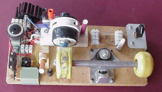
The network to which I'm referring comprises four resistors and a couple
of wire links connected into two four-connector terminal strips, along
with a single-pole, four-position rotary switch. It's installed in the
top-right quarter of the base-board, as you can see quite clearly in the
photo above. (The small white pillar just below the right-hand terminal
strip is not part of the network; its function has already been
explained in the earlier page.)
The network exists to allow me to vary the 340-ohm series resistance (a
10-ohm resistor in series with a 330-ohm resistor), which is part of the
motor's trigger circuit (when running the motor from an external power
source), from 340 ohms down to 10 ohms via two other possible values,
105 ohms and 32 ohms respectively.
In the following photograph (already presented in the previous page), you
can see the 330-ohm resistor just mentioned connected into the right-hand
side of a small black terminal block near the switch, at lower left:
I later added the resistor network which is the main subject of this page,
and connected it in parallel with that 330-ohm resistor via a pair of
yellow wires which run behind the coil's platform, as you can see above.
Prior to doing so, the circuit diagram (also presented in the previous
page) was as follows:
(The "variation 2" in that diagram refers to the fact that the 330-ohm
resistor itself was originally not part of the circuit.)
Now, with the resistor network and its rotary switch installed, the
circuit diagram can be modified thus:
As pointed out in the previous page, the 330-ohm resistor and the network
in parallel with it are effectively part of the circuit only when
the motor is being run from an external power supply. When it's running
from the on-board 9V battery, they are shorted out by the main switch.
When an external supply is used, with the four-position rotary
switch it's now possible to have any one of four values for the trigger
circuit's series resistance.
With the rotary switch set to its fully anticlockwise position (A), the
network is switched out of the circuit, so that the series resistance is
10 + 330 = 340 ohms.
With the rotary switch set to its fully clockwise position (D), the
network is effectively a short circuit, and the 330-ohm resistor is thus
shorted out. In this case the series resistance is simply 10 ohms.
So, the situation is as follows:
At position A, effectively we have an "infinite" resistance in parallel
with the 330-ohm resistor; whereas at position D, we have a zero
resistance in parallel with it. Between these two extremes, it's possible
to have two other settings of our four-position rotary switch which can be
used to connect finite, non-zero resistances in parallel with the 330-ohm
resistor, thus producing two other actual values for the series
resistance. The question which arises is: what other values?
Before addressing that question, it's as well to point out that you don't
have to use a four-position switch. We could, if we liked, simply
use a two-position ("double-throw") switch to accomodate the two options
discussed so far, and not bother with any other possible settings. Or, if
we wanted to go to extremes, we could use a multi-position switch and thus
accommodate lots of other possible settings.
It's possible to buy rotary switches with up to 12 different settings (or
perhaps even more, in some places). I could have done that; alternatively,
I could have a rummage through my Dad's old things and see what I could
find - and that's exactly what I did.
Anyway, I was delighted to find this old thing, and decided that it
would do very nicely as a selector switch for the resistor network in my
first monopole motor, adding a lovely "olde-worlde" touch to the
proceedings! Here are some photos of it:
It needed a bit of cleaning up. The shaft was dark brown; at first I
thought it was badly-tarnished brass or copper, but when I started work on
it with an industrial-strength metal-cleaning product containing
phosphoric acid, the brown stuff eventually came off, and I found to my
surprise that the actual metal was a dull grey - just iron, it seems. The
brown stuff, apparently, was quite simply many decades-worth of rust!
Okay - so I had a four-position switch. As mentioned, its "off" position
(fully anticlockwise) was perfect for the "infinite resistance" setting,
and a simple wire link to its fully-clockwise terminal would serve for the
"zero resistance" setting. What about the other two positions?
Two logical possibilities presented themselves: either use resistors which
would place the four values of the series resistance in
arithmetic progression
(AP), with a common difference; or use resistors which would
result in those four values being in
geometric progression
(GP), with a common ratio.
Somewhat arbitrarily, I chose the GP option. (As it turns out, experience
has shown that I seem to have made the right choice.) So I needed to
calculate resistances R1 and R2 such that R1/10 = R2/R1 = 340/R2 (each of
those three numbers thus being equal to the common ratio).
As is usual for GP problems, let's call the common ratio "r". Then we
require that
r3 = 340/10 = 34
Then r = the cube root of 34 = 3.24 (to two decimal places); then
r2 = 10.50 (also to two decimal
places), or simply 10.5 . Thus our two resistance values need to be 10
ohms × 3.24 (= 32.4 ohms) and 10 ohms × 10.5 (= 105 ohms) respectively.
Note - those two values are not the resistors we need to place into
the circuit (at C and B respectively)! We're not finished yet. We still
have to calculate the values of the two required resistors, R1 and
R2.
Consider R1 first. We need it to have a value such that, when placed in
parallel with the 330-ohm resistor, the resistance of the parallel
combination - plus the 10-ohm resistor - will equal 32.4 ohms.
If you know some basic circuit theory, you'll know that the resistance of
a parallel combination of two resistors is their product divided by
their sum. So we require:
330 × R1 / (330 + R1) + 10 = 32.4
- or 24 ohms, near enough.
You can't buy 24-ohm resistors, but you can buy 12-ohm resistors. If I'd
had two 12-ohm resistors, I could have simply connected them in series and
placed them at C - but I didn't have them. So rather than go out and buy
them, I had a hunt around to see what else I could find that would do
instead.
I had a few 47-ohm resistors lying around (six of them, to be exact). Now,
if you put two 47-ohm resistors in parallel, the resistance of the
combination is 47 × 47 / (47 + 47) = 23.5 ohms. I figured that that was
close enough! So that's why there's a parallel combination of two 47-ohm
resistors at C on the circuit diagram above.
What about the other resistor, R2 (which needs to go in at B)?
Going through the same procedure as above, but with 105 in place of 32.4,
we obtain:
330 × R2 / (330 + R1) + 10 = 105
- or 133 ohms, near enough.
Now, 133-ohm resistors are not commercially available either; but 100-ohm
and 33-ohm resistors are - and I happened to have at least one of each in
my spare-parts collection. So a series combination of these fitted the
bill perfectly, and was duly installed at B.
I suppose I could have simply used a three-connector terminal strip on the
left - or even a two-connector strip - just to hold the corresponding ends
of the resistors, and simply run wires along the base-board for the top
link, or the bottom one, or both. (At a pinch, I could also have got away
with a two-connector strip on the right, connecting the yellow wires
directly to the switch.)
However, I decided it would be worth the extra bit of effort to make a
neat job and use two four-connector strips, with insulated wire links
connecting their ends. (It also probably helps to make the circuit easier
to follow.) So that's what I did, as shown in the following diagram:
Having thus constructed the resistor network, using my multimeter I found
that the actual resistance values were slightly different from those
calculated. This is basically because commercial resistor values are never
exact anyway; depending on what type of resistors you buy, they're within
5% or 10% of the stated value (you can get resistors with 1% tolerance,
but they're more expensive and probably scarcer - depending on where you
live - and generally not worth the bother for most practical purposes).
So now you know!
Here's a little problem for you:
If I'd decided to have the four series resistance settings in AP rather
than GP, what values would have been needed for R1 (at C) and R2 (at B)?
To do this, you'll need to work out a common difference, instead of
a common ratio. Then you can essentially follow the same procedure
as for the GP case as shown above.
Remember: the "ABCD" network (and its associated rotary switch) still
needs to be connected in parallel with the 330-ohm resistor, with the
10-ohm resistor connected in series, just as before.
Go on - exercise a bit of will-power and work it out yourself, before
clicking
here
to check your answer.
My home page
Preliminaries (Copyright, Safety)
 Mad Teddy's researches
into zero-point energy
My first "monopole motor"'s resistor network
>>>
Nikola Tesla's 153rd birthday
<<<


 I found a
little rotary switch which had an "off" position ("infinite" resistance)
and three "on" positions - four positions altogether. It had probably seen
service long ago in an old valve radio, perhaps with a medium-wave setting
and two short-wave settings. (Remember short-wave radio? It's still there
- and it's still fun to have a "listen-in"!
I found a
little rotary switch which had an "off" position ("infinite" resistance)
and three "on" positions - four positions altogether. It had probably seen
service long ago in an old valve radio, perhaps with a medium-wave setting
and two short-wave settings. (Remember short-wave radio? It's still there
- and it's still fun to have a "listen-in"!  )
)


=> 330 × R1 / (330 + R1) = 22.4
=> 330 × R1 = 22.4 × (330 + R1) = 7,392 + 22.4 × R1
=> (330 - 22.4) × R1 = 7,392
=> R1 = 7,392 / 307.6 = 24.03 (to two decimal places)
=> 330 × R2 / (330 + R2) = 95
=> 330 × R2 = 95 × (330 + R2) = 31,350 + 95 × R2
=> (330 - 95) × R2 = 31,350
=> R2 = 31,350 / 235 = 133.40 (to two decimal places)

 Return to my My first "monopole motor" page