
PLEASE NOTE
If you've come here by way of my
High-voltage projects sub-menu
, you will have seen my warnings on electrical safety. If you haven't read
this yet, please click on that link and do so before proceeding.
If you're browsing my website by following the menu system, you will almost
certainly have seen this picture before. It's a photograph of this project
operating.
As mentioned in my
Induction coils projects
sub-sub-menu, an auto ignition coil is a type of induction coil. Whereas a
"traditional" induction coil has its own interrupter (a built-in buzzer-like
arrangement operated by the induction coil's own magnetic field), a
motor-vehicle's ignition coil is activated at exactly the right moment by
the rotation of the engine itself.
A rotating device called a distributor is mechanically coupled to the
engine so that, just when one of the cylinders needs to fire, the ignition
coil's output is delivered to the appropriate spark-plug.
In the original old Kettering system, a cam on the distributor's shaft
operates a set of "points" which quite simply make and break an electrical
contact, thus switching on and off the ignition coil's primary winding. So
these points do the same job as the interrupter in a traditional induction
coil. The usual sequence of events then occurs. A rotor on the end of
the distributor shaft connects the high-voltage secondary output to the
appropriate spark-plug. A capacitor (about 0.1 microfarad) connected across
the "points" ensures that the spark is powerful enough to ignite the
fuel/air mixture in the cylinder.
In more modern vehicles, an electronically-operated system replaces the
points, which are probably the "weakest link" in Kettering systems. In
principle, these electronic systems should give rise to a better spark.
This link
explains both the Kettering system and the newer electronic systems rather
well.
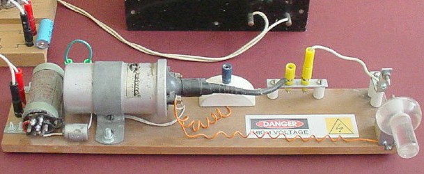
It's possible to use an ignition coil to build a spark coil which operates
apart from an automotive environment. Here's mine:
In addition to "Old Sparky" (foreground), you can also see portions of my
power supply and bridge rectifier
(top centre and top left, respectively), which I use to power the coil.
If you've already seen my
Electrical / electronic projects
page on your travels leading to this page, you'll know that the "eighth
edition" of "The Boy Electrician" (1965), by "ARMAC", featured an induction
coil circuit built around an ignition coil. The original version of this
project, built by my Dad, was based largely on that circuit.
This is the circuit diagram for the unit after I revamped it in 2002:
Notice that the primary and secondary of the ignition coil are connected
together at one end. This is not something I've done; ignition coils are
manufactured that way (the connection is inside the case). The reason is
that, in a car ignition system, both coils need to be "earthed" to the car
body; so this is a way of making that possible using only one
external connection.
Unlike "traditional" induction coils, in an ignition coil the primary is
wound over the secondary, which is wound first (see
this link
for a good diagram). The inner end of the secondary is connected directly
to the high-voltage terminal in the apex of the plastic cone, and the outer
end is connected to one of the two low-tension terminals, with the primary
connected directly between these.
(It is possible to get the case off and break the inter-coil connection;
however, the device may be damaged as part of the process. For this project,
it's not necessary - it's fine to leave the ignition coil as it is.)
Another thing that you might find a bit surprising is the fact that the
negative line is "on top", and the positive line is "on the bottom",
contrary to usual practice. Why?
One of the primary terminals on the black plastic conical end of the
ignition coil (the nearer one, in the picture) is marked "+"; the other is
marked "-". The "+" terminal is connected to one end of the spark gap at the
right (again, the nearer end) by a longish piece of loosely-coiled orange
wire.
This is how it was when I discovered it in 2002. My Dad presumably wired it
that way because the coil was originally from an old-fashioned
"positive-earth" car (whether he knew that, or just assumed
it, I don't know). Either way, that's very probably the explanation for the
way it's wired! (Even simple things can be quite complicated, can't they?)
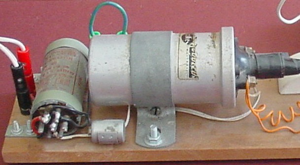
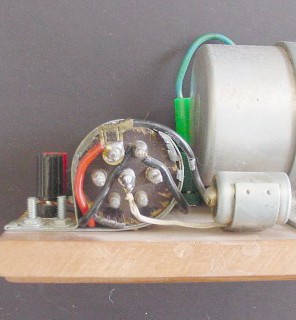
Here's a close-up of the ignition coil, the vibrator, and the capacitor.
The capacitor is the small cylindrical object below the left-hand end of the
coil. It's of the type normally used in car ignition systems. The case forms
one electrode; the other electrode is centrally located at the left-hand
end. I've used a slightly unusual symbol for the capacitor in the circuit
diagram above just to indicate that the case is connected to the ignition
coil - the common connection of the primary and secondary mentioned above.
(The capacitor would work equally well if it were connected the other way
around.)
The larger cylinder at the extreme left is the vibrator from an old car
radio. This is the device which switches power to the ignition coil primary
on and off.
Until the 1960's, when transistors became easily and cheaply available,
radios utilized valves (called tubes in the US). This applied to car radios
no less than any other radios. In order to function, valves require a fairly
high voltage. In a domestic radio, this was no problem - the mains voltage
did the job very well. In a car, however, available voltages are
considerably lower; hence a method had to be found to produce a high enough
voltage. The vibrator was the device used.
Such vibrators are thus pretty much a thing of the past. Strange, is it not,
to think that there was a time when you could go to your local electronics
outlet and casually ask for a new vibrator without causing any raised
eyebrows?
Just imagine a modern advertisement for one of these, if they were still
a hot item: "Put a spark in your life with a new vibrator from your local
Mad Teddy Electronic Novelties store!"
I don't want to get into the details of how these vibrators work; it's a
minor study in its own right. If you're interested,
this link
gives a good explanation.
Suffice it to say that I've got mine operating essentially as a buzzer. The
note it produces is approximately F# below middle C. Since A below middle C
has a frequency of 220Hz, and F# is three semitones (a quarter of an octave)
lower, the vibrator's frequency is about 220Hz divided by the fourth root of
2, i.e. 185Hz.
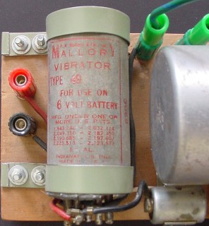
You'll notice that only three of the seven available terminals are used. As
I recall, without getting it out of its battered old aluminium case and
possibly damaging it even more, there are two sets of contacts in it;
I'm just using one-half of one of them. (Presumably, this
vibrator was of the synchronous type - see the link above for
details.)
When I dug "Old Sparky" out and did it up it in late 2002, I found that my
Dad had originally wired four of the vibrator's terminals. I never
quite figured out why; presumably, he was using both halves of one set of
contacts (which would have doubled the spark frequency). It wasn't working
well, so that it was necessary for me to get into it and try to figure out
how it worked and effect a repair job. I hadn't found anything useful about
vibrators on the internet at that stage, so I had to nut it out myself. I
re-wired it using just three terminals, as a buzzer, and it worked fine. (I
think it was a good thing to do, because the fewer moving contacts there
are in a circuit, the less there is to go wrong. The spark frequency isn't
really an issue!)
One minor problem is that, after some use, the contacts obviously became a
bit corroded (even with the capacitor in the circuit) and it didn't want to
start. I could pull it out of the case and clean them; but, as mentioned
above, I'm loath to do that because the case is already somewhat the worse
for wear. I've found that just giving the case a light tap with a
screwdriver or similar is enough to get it started; then it keeps going with
no problems until switched off.
Two close-ups - the printing on the vibrator; and its connections:
You don't have to use a vibrator! The main reason I've kept mine in
the project, with all its faults, is for old time's sake. If it plays up too
much, I'll try to fix it; eventually, if it's too far gone, I'll just
replace it with a relay wired up as a buzzer.
A basic relay, easily obtained from an electronics shop, will do fine, wired
so that the coil is in series with the normally-closed contacts (some relays
have two sets of contacts; either will do). It's best to use a well-built
sturdy one with high-quality contacts as used for high-current switching, so
that it will last the distance.
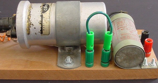
Here's a view from behind the coil and vibrator:
The two green banana terminals correspond to the points "A" and "B" on the
circuit diagram (see above); in this view, "A" is the terminal on the right,
and "B" is on the left. According to some sources (see
this link
, for example), there should be a current-limiting "ballast" resistor
between these two points. Probably, if we were using a car battery or
similar, this would be a good idea; but I've had no problems running the
project from my old power supply / bridge rectifier setup just using a piece
of wire (green, with green banana plugs) to connect them together directly.
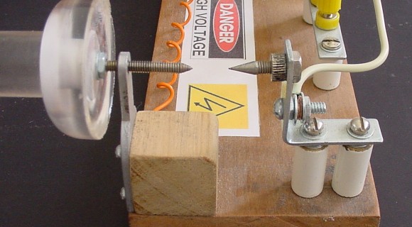
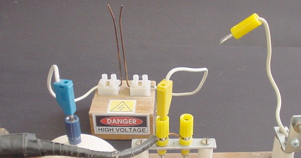
Now for a detailed look at the right-hand half of "Old Sparky":
Features:
Firstly, and most importantly, those warning signs aren't there for a joke.
Let me tell you a little story:
If you've visited my
synchronous wheel
pages, you may recall that I used to have a small neon light globe, about
the size of a 15-watt pilot light, to play with. It had a standard size
bayonet fitting. (It's been missing for ages - I've no idea what's happened
to it.)
Anyway, years ago, before I lost "Old Sparky" and found it again, one day I
decided it would be interesting to see how the neon light would respond to
twenty-something thousand volts across its terminals. So I switched "Old
Sparky" on and held the light over the spark gap (such as it was back then).
It lit up all right - but so did I, as sparks also climbed up over the
outside of the glass to my waiting fingers.
The voltage is high, but the current from such a circuit is pretty low. It
may not kill you (although you never know) - but it can certainly
make your eyes water!
Secondly, the output terminals. The blue terminal is connected to the common
"earth" connection of the primary and secondary (the coil terminal marked
"+", in this case). So this is the low-voltage terminal of the output. The
high-voltage output - the thick lead from the apex of the black plastic cone
on the right-hand end of the coil - is connected to the left-hand yellow
terminal. I placed these two terminals there so that if I ever wanted to use
the output to run another project - a Jacob's ladder or a small Tesla coil,
for example - it would be easy to make the connections. (The blue terminal
projects from a small white-painted curved piece of wood sawn off the top of
a corner post from an old baby's cot. Er - that's the cot that's old, not
the baby.
Thirdly, the spark gap. This can be seen at the extreme right-hand end of
the photograph. As already mentioned, the near end is connected to the "+"
terminal of the coil and the blue terminal. The far end is connected by a
short wire to a yellow banana plug which is then inserted into a second
yellow terminal connected to the first by a metal strip, made by flattening
out a small right-angle shelving bracket (which is then supported above the
base by two small porcelain insulators - more treasures which I found among
my Dad's old things!). If it is desired to disable the spark gap, it's only
necessary to pull the yellow plug out and leave it suspended at the end of
its short stiff white wire. (Important: the unit must be switched off
before connecting or disconnecting the spark gap!)
The far (high-voltage) end of the spark gap is a metal spike from a defunct
old-fashioned voltmeter (guess where I found it
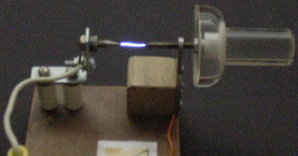
Here's a view of the spark gap, taken looking toward the end of the unit:
- and here it is doing what it does best (seen from the other side):
Running it from my old power supply set to maximum, with the bridge
rectifier to give about 27V DC (which "Old Sparky" doesn't seem to mind -
even without a ballast resistor!), I can regularly get a consistent 2.1cm
spark from it. Depending on which source you read, this could represent
anything up to about 25,000 volts, or possibly more.
On a good day, possibly depending on such things as humidity, I can widen
the spark gap to about 2.2 cm and still get intermittent sparks.
It's not the biggest, most impressive sparky thing on the internet - I'm
well aware of that. But it's about what you can expect from an ignition
coil, and it's pretty consistent. It's certainly big enough to give you
quite a surprise if you get too up close and personal with it - believe me,
I know!
Here's a 10-second movie (231.6Kb) showing the action:
sparkgap.mpg
Having dug the old thing out, tidied it up and got it working quite nicely,
the next obvious thing to do was to make a little Jacob's Ladder.
Here it is:
It's just a couple of short pieces of mains wiring, stripped, bent into the
traditional shape and mounted in terminal blocks. It's connected to the
output terminals mentioned earlier by means of fashionably-matching banana
plugs. Note that I've disconnected the spark gap by pulling the other yellow
plug out; it's not strictly necessary to do this, as the Jacob's Ladder
width is less than the usual spark gap setting, but since I provided the
option I might as well make use of it.
Here's a 5-second movie (119.6Kb) of the Jacob's Ladder doing its thing:
jacoblad.mpg
It's not impressive enough to pass the audition for a B-grade science
fiction / horror movie; but it illustrates the principle. It really needs to
be left on for a few minutes to allow the wires to get warm, in order to get
the obvious upwards movement of the sparks and the satisfying
"whoomp-whoomp-whoomp" as they disintegrate at the wide part at the top; for
some reason, when I was filming, it didn't want to perform to expectations.
Them's the breaks.
If you look very carefully at the sparks (pausing the action helps, if your
mpeg player allows you to do that), you may notice that the right-hand end
of the spark (negative) is yellowish, whereas the left-hand end (positive)
is bluish or purplish. (Remember: we're looking at the project from
behind, so that the polarities are reversed from the front view.)
I'll admit, it's not too obvious from the movie; but if you could see the
thing in real life you'd be convinced. The effect is quite pronounced.
Here's an appropriately gloomy close-up taken from in front (so that left is
negative and right is positive):
There is a definite touch of yellow toward the left, and at the right-hand
end the spark is more intense and bluish. What are we to make of that?
I'm by no means an expert on this subject; but
this excellent link
, which deals in detail with how Wimshurst machines work, may throw some
light on the matter. (Have a good look around this gorgeous site. Its author
is definitely a - perhaps the - world authority on electrostatic
machines, of which he has built a large number - as well as describing other
high-voltage projects.)
Over the last couple of days I've had the ignition coil circuit and the
Jacob's Ladder running again. I took a 15-second, 1.3Mb mpeg movie, which
shows the action somewhat better than the original. Click
here
to see it.
That's it, basically! Foolish but fun. If you ever decide to make such a
thing, it will give you some amusement - but just keep those fingers away
from the "hot" bits!
My home page
Preliminaries (Copyright, Safety)
"Old Sparky": my ignition coil circuit
(ca. 1967)


Mad Teddy's Ignition Coil Circuit - spark gap


 Yeowwww!
 )
), attached by a nut to
another right-angle shelving bracket (mounted on two more porcelain
insulators). The near (low-voltage) end is a bolt, sharpened to a point,
which is set into the threaded hole of a strange small shaped piece of sheet
metal I had lying around. This is attached to the base via a small wooden
block. This end of the spark gap is adjustable by means of a knob made from
some surplus bits of transparent casting resin.
)
), attached by a nut to
another right-angle shelving bracket (mounted on two more porcelain
insulators). The near (low-voltage) end is a bolt, sharpened to a point,
which is set into the threaded hole of a strange small shaped piece of sheet
metal I had lying around. This is attached to the base via a small wooden
block. This end of the spark gap is adjustable by means of a knob made from
some surplus bits of transparent casting resin.

UPDATE
Friday, 13th March 2009
 Return to Induction coil projects sub-sub-menu